Apparatus – Measuring principle
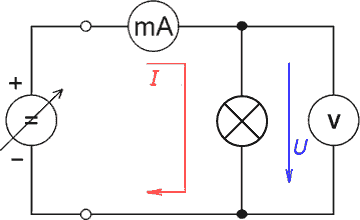
As in the case of the Voltamper LED characteristic, the principle of the task measurement is based on the standard V-A characteristic of the general electronic element. Using a variable source, we vary the voltage across the element to be measured (in this case, the bulb) and read the magnitude of the current on the ammeter connected in the circuit. The V-A characteristic in this task is measured point-by-point, i.e. the gradual measurement of voltage-current pairs in the set range of values. The circuit diagram is shown in Figure 1.

Fig. 1 – Schematic diagram of the bulb V-A characteristic measurement experiment
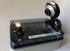
In the case of our remote VeLMA experiment, we use the same scheme, except that the K8055 measurement board is replaced by the regulated source and the measurement instruments. One of the two digital-analogue outputs is current-enhanced and serves as a regulated source with a maximum voltage of about 5 V. The analogue-digital inputs act as a pair of voltmeters. One measures the voltage across the bulb, the other measures the voltage across the resistor. Knowing the voltage across the linear element (resistor), Ohm's law can be used to determine the current flowing through the resistor and therefore the bulb – see diagram (Figure 1). The effect of the current flowing (e.g. the moment when the bulb lights up, the intensity of its light, etc.) can be observed using the connected webcam.
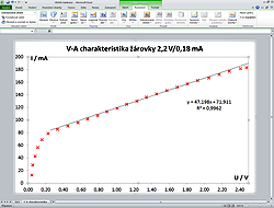
Both measured experimental values (i.e. U and I) are read and displayed on the control panel in a client-side web browser. Such measured values can be stored in a table (file) and continuously displayed on a graph. The continuous display of values in a graph directly on the task measurement panel is primarily for orientation, to check the accuracy of the measured data, or to find the locations of the characteristics where the required data needs to be collected. For complete processing according to the assigned task, the data can be stored on your PC and processed there in any spreadsheet program – MS Excel, OO Calc, etc.

As the device is very similar to the NICoL (Voltamper LED characteristic), it has been implemented together on the same K8055 USB card. However, the tasks have now been solved so that they can be controlled independently, although a single control card is used for both tasks. The independent management of two tasks with a single K8055 card is currently (according to available information) unique worldwide!
Video tutorial
TURN ON THE SUBTITLES IN THE VIDEO TO SEE THE DESCRIPTION AND EXPLANATIONS!


