Theory
Voltamper characteristic
The volt-ampere characteristic is one of the basic characteristics of electrical and electronic elements. The volt-ampere characteristic is a graph of the current flowing through the device versus the electrical voltage connected to the device. It is only the basic shape of the characteristic and the general course of the current and voltage dependence that tells us much about the electrical element. The shape of a curve can be influenced by many parameters. Thanks to this, the "volt-ampere characteristic" can also be the whole system of curves of dependence of the current on the voltage, the shape of which is influenced by some other variable as a parameter – e.g. volt-ampere curves at different temperature, pressure, magnetic induction, etc.
Most components or devices have a linear voltamper characteristic. In some cases the voltamper characteristic is not completely linear, but for simplicity small non-linearities are neglected and the components are considered linear. For example, consider a resistor. Conversely, non-linear components have a voltamper characteristic in the form of a non-linear curve, such as an exponential, but also other curves (diode, thermistor, stabiliser, rectifier…).
Static and dynamic electrical resistance
Static resistance:
For conventional devices, such as resistors, the relationship between electrical voltage and current is referred to as the electrical (static) resistance of the device. If the resistance of the device is constant, the voltage-to-current dependence of the Ohm's law and the current-to-voltage ratio are linear. Electrical resistance is given by:
where U is the voltage across the device and I is the corresponding current flowing through the voltage at the given voltage.
Since the curve is a straight line, the resistance is still the same and can be calculated from any pair of corresponding values using the relationship (1). The resistance value R also corresponds to the linear volt-ampere characteristic.
Differential (dynamic) resistance:

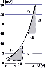
Fig. 1 – Example of a non-linear V-A characteristic
If the resistance of the device is constant during the passage of the current, the graph is the general function I = f (U). In such a situation, the static resistance can also be calculated, but it is no longer a constant that uniquely describes the element. The amount of static resistance varies according to the selected voltage and current pair (depending on the position of point P). In Figure 1 we see two points in the example of non-linear dependence. At point P1 there is a static electrical resistance of R1 = 3 V/25 mA = 120 Ω, while at point P2 the value of the voltage and current ratio R2 = 1 V/5 mA = 200 Ω. These resistances have their meaning, for example, in solving the energy conditions in the circuit or in determining the load of the element. On the other hand, the static resistance is inappropriate when we want to describe the behaviour of an element under a small change of conditions (as described in the curve directive). For this purpose, the so-called electrical differential (dynamic) resistance is introduced.
Its meaning can be illustrated as follows: If the voltage ΔU changes very little about the value of U around a given point P, the resulting current will change by changing ΔI as if it were moving along a line fixed at point P (see Figure 1). The value of the directive on this line determines the magnitude of the differential dynamic resistance. Its value in turn depends on the position of point P (compare the inclined gradient at points P1 and P2 in Fig. 1) and is determined by the non-linear dependence of the element by measuring the differences ΔU and ΔI or theoretically by calculating the derivative:
The differential resistance curve shows the tendency of the element to increase or decrease. Specifically for the bulb, the electrical resistance (static and dynamic) of the bulb filaments depends on temperature ("ignition"). The bulb has a metal filament which heats up greatly as the current passes through it, and its resistance is greater when operating than when cold – see Temperature dependence of the metal resistance.
Bulb
Thermal light source
The largest and oldest group of artificial light sources are thermal, or incandescent. Incandescence is the phenomenon of light emitted by thermal excitation. In these sources, light is produced as one of the components of electromagnetic radiation induced by the high surface temperature of a body (burning paraffin candles, passing the electric current through the fibre… etc).
Conventional incandescent light bulbs work on the principle of an incandescent filament – a high temperature is induced by passing an electric current through a high-melting, conductive substance such as carbon or tungsten. The solid is heated to the desired temperature at which visible light is emitted. Tungsten (in the case of the first carbon bulbs) is burned in the bulbs.
The common characteristics of temperature sources are:
Very low light energy conversion efficiency (efficiency increases with power consumption),
a large proportion of the energy emitted in the form of heat (the bulk) compared to visible light,
continuous distribution of light in the spectrum,
subjectively pleasant perception of light by the human eye.
Lamp specific power
The specific power of a light source indicates the efficiency of the conversion of electrical energy into light. It is equal to the ratio of the luminous flux (lm) emitted by the source to its electrical input (W). The specific power is used to compare the efficiency of light sources. It is called η [eta] and is expressed in lumens per watt (lm/W). If it were possible to prevent the source from emitting at wavelengths other than visible, we would have a luminous efficiency of 251 lm/W. This is the theoretical maximum that artificial white light sources can approach. It is only 37 % of the maximum efficiency of the monochromatic source, which is 683 lm/W.
Table no. 1: Approximate values for some conventional light sources.
| source |
type |
Specific output power
(lm/W) |
Wattage
(W) |
| Bulb |
classic |
6–16 |
15–200 |
halogen
(mains voltage) |
24–30 |
60–2000 |
halogen
(12 V voltage) |
11–19 |
5–75 |
| Compact fluorescent lamp |
"Energy saving bulb" |
50–87 |
5–55 |
| LED white |
|
20–150 |
0.04–180 |
High pressure
sodium lamp |
conventional
street lights |
70–130 |
50–250 |
source: Měrný výkon světelných zdrojů aneb účinnost podruhé. ARIGA S.R.O. FotonMag.cz:
aneb nejenom LED, svítilny, baterky a baterie v jiném světle [online]. 28. 12. 2007 [cit. 2015-08-14].
Dostupné z: http://www.fotonmag.cz/osvetleni/merny-vykon-svetelnych-zdroju-aneb-ucinnost-podruhe/
Bulbs as light sources
Incandescent light bulbs are the most common type of thermal light source. Due to their wide range, low installation and maintenance requirements, incandescent lamps are now widely used as light sources. Conventional incandescent lamps have a specific output of only 6–16 lm/W. For halogen lamps, the efficiency of the halogen regeneration cycle is up to 30 lm/W. A major drawback of incandescent lamps is the switching current, which is up to ten times the nominal current (see below) due to the low resistance of the cold fibre.
The temperature of ordinary incandescent lamps in the 40–200 W range is between 2000 °C and 2640 °C. For lower wattage bulbs the temperature is lower. Threading the fibre at such high temperatures causes gradual erosion of the fibre as the evaporated tungsten is deposited on the inner wall of the bulb. This reduces the cross section of the fibre and changes the parameters of the entire bulb. To prevent the fibre from bursting immediately, it is placed in an ordinary glass jar from which the air is extracted. For standard 15 W lamps, the bulb is usually vacuum-filled, with more powerful bulbs being filled with nitrogen and argon, or (less commonly) krypton or even xenon. These fillings allow higher operating temperatures of the fibre and reduce ageing due to sputtering or evaporation. For standard and large bulbs, the fill is chosen so that the pressure inside the bulb is close to atmospheric pressure. The statistical life of conventional bulbs is approximately 1000 hours of illumination.
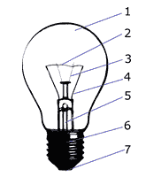
- Glass fask
- Tungsten fiber
- Carrier hooks
- Inlets
- Pumping (evacuation) tube
- Socket
- Central contact
Fig. 2 – Main parts of the classic bulb

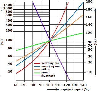
Fig. 3 – Effect of voltage on basic bulb parameters.
source: HABEL, J. a kol.: Světelná technika a osvětlování.
FCC Public, Praha, 1995, ISBN 80-901-9850-3
The light output of the lamp depends on the current that heats the fibre. Any heat source should be operated at rated parameters (most commonly rated voltage). Reducing the supply voltage by 5 % will reduce the luminous flux of the lamp by approximately 18 %. Increasing the rated voltage by 5 % will increase the luminous flux by approximately 24 % but will reduce the lamp life by 50 %! (See Figure 3) Overloading the lamp will therefore result in a significant reduction in lamp life.
The luminosity of the lamp also has a significant effect on how often it is switched on. The worst current peak for the lamp is when it is switched on when the fibre is cold and the shock is very strong (up to ten times the nominal current). Halogen lamps are even more sensitive to this start. One way of limiting the impact of starting and stopping is to use a so-called soft-start circuit, which allows the bulb to flash slowly (1–3 s), thus increasing its life (up to 5×). Or, in the case of directional car lights, for example, the flicker frequency can be set to prolong the life of the bulb by preventing it from cooling down completely due to the thermal inertia of the filament.


