Apparatus
Measurement Principle
Fig. 1 - Tangent Compass
zdroj: http://vnuf.cz/sbornik/prispevky/ soubory/04_21/image002.jpg
The classical method of measuring the horizontal component of the earth's magnetic field is the tangent compass method. It is a device (Fig. 1) consisting of a circular coil with a larger average diameter and a small number of coils arranged in a narrow beam. In the center of the coil is a small magnet that rotates around a vertical axis.
Before measuring coil stand so that its plane coincided with the plane of the magnetic meridian, and thus the magnetic direction. Begins to flow through the coil current I arises at magnetic field whose magnetic flux is given by the vector magnetic field and magnetic field generated by the coil (see Figure 2).
Fig. 2 - composition of the magnetic vectors
Due to the field coil, the vector is perpendicular to the horizontal component of the earth's magnetic field, the magnet is deflected from its original position by an angle φ and take a new equilibrium corresponding to the direction of the resultant magnetic field induction (Fig. 2). Substituting the formula for the magnitude of the vector into the valid relation:
we obtain the final expression for the Earth's magnetism as a function of the current in the power coil (can be measured with an ammeter) and the deflection of a compass (can be read with a compass).
Measuring apparatus
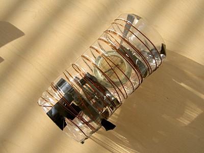
In practice, we usually have in the collections of tangent direction finding, we can measure the BH improvise. To improvise you can use a simple solenoid of copper wire wound for packaging plastic bottles, cardboard fastened to the tourist compass (see right picture). For the relationship between electric current and magnetic induction coil then we substitute the classical expression for the solenoid.
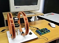
In our laboratory we are not prepared for this experiment a little more sophisticated design. We have contacted several people who have experience with this experiment and we have suggested the following report. The principle is still the same, but instead of a simple circular coil, we used a special pair of coils, called Helmholtz coils*) because of their configuration. By using Helmholtz coils, we not only have better access to the compass and thus its readability, but also more homogeneous magnetic field coils. Finally, we wanted to make high school students familiar with these coils, which are often used in practice and yet the hours when they talk about physics. The expansion will follow the relationship for the magnetic field in the center of Helmholtz coils.
| *) |
A Helmholtz coil pair consists of two identical circular magnetic coils placed symmetrically on either side of the experimental area along a common axis and separated by a distance equal to their radius. The current through the two coils is the same and uniform direction. The resulting field between the coils is nearly homogeneous. |
Measurement – Applicable Relationships
Based on the above equation (1), where B is the magnetic induction coil that deflects the compass needle by an angle φ from the direction of the local magnetic meridian, i.e., the direction of the horizontal component of the Earth's magnetic field BH.
Substitute the expression for the magnetic induction Helmholtz coils:
we obtain the final relation:
| that: |
| N |
|
– number of turns of each coil; N = 240 |
| r |
[m] |
– radius of the coils (also distance between coils); r = 15 cm |
| I |
[A] |
– electric current in the coils |
| φ |
[°] |
– deviation of the magnetic needle corresponding to the current I; |
| μ0 |
[T·m/A] |
– permeability of vacuum (air); μ0 = 4π ·10–7 T·m/A |
Just a few measured values of the excitation coils of the electric current I and the deviations φ. Searched value of the horizontal component of the magnetic induction BH Earth can then be determined as the arithmetic mean of partial results.
Spreadsheet processing (without specifying the value of B):
When we realize that the obtained relationship (3) can be changed into:
which shows that the relationship between the values of the functions tg φ and current I is linear (even directly proportional!). If we have enough measurements for different angles of deflection of the magnetic needle and the corresponding current coils, we can plot the values of tg φ and current I on the graph. A look at the shape of the graph convinces us that our description of the dependence is correct. If it was not a linear dependence, it means that the measurements may be affected by some bias – such as bad in the rotating compass needle, etc.
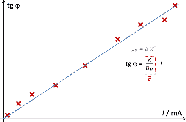
Fig. 1 – Dependence of the value of the tangent of the deflection angle on the driving current of Helmholtz coils
Using a spreadsheet program (MS Excel, OO Calc, etc.) it is possible to obtain the value of the parameter a – see Fig. 1 and expression (4) – by linear regression. This value is the ratio of the constant expression K and the desired value of the horizontal component of the earth's magnetism BH. The locally valid value of the horizontal component of the earth's magnetic induction is obtained by dividing the constant expression K by the numerical value of the directive a.
Video tutorial
TURN ON THE SUBTITLES IN THE VIDEO TO SEE THE DESCRIPTION AND EXPLANATIONS!