Theory
Electrochemical (Galvanic) Cells
There are a number of physical principles that make it possible to convert other forms of energy into electrical energy. The most widespread of these "surrogate sources" are electrochemical sources which, either irreversibly (so-called primary cells) or reversibly (secondary cells, also called accumulators), allow the chemical energy of certain chemical reactions to be converted into electrical energy.
The advantage of electricity is that it can be easily transmitted over long distances and is relatively easy to convert into other forms of energy. But there are also disadvantages. The main one is the very poor efficiency of electricity storage. And true electrochemical cells are designed to store electrical energy with the highest possible efficiency.
Zinc primary cells:
Primary cells with a Zn anode are still the most common electrochemical power source. Their nominal voltage is 1.5 V. This group includes the following commonly manufactured electrochemical systems:
MnO2/Zn with slightly acidic electrolyte, mainly NH4Cl (Leclanche's cell)
MnO2/Zn with slightly acidic electrolyte, mainly ZnCl2 (zinc chloride cell)
MnO2/Zn with alkaline electrolyte (alkaline cell)
Battery systems made from manganese dioxide zinc with a slightly acidic electrolyte are often referred to as zinc-carbon batteries, although the carbon is not an electrochemically active material, only a current collector. Sometimes these batteries are referred to as zinc-burel cells, which may be more accurate. And to keep the naming scheme simple, these cells are also known as dry cells because the electrolyte is immobilised (not in a liquid state).
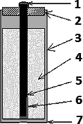
1. Leclanche's cell
The Leclanche's cell is an electrochemical source of the system: manganese zinc oxide (MnO2Zn) with a slightly acidic electrolyte with a predominance of NH4Cl (salmon). This is the first type of chemical energy source to be mass-produced. In the Leclanche cell, zinc is used as the anode, manganese dioxide as the cathode and ammonium chloride as the main part of the electrolyte, but some zinc chloride is present in the electrolyte. Zinc is oxidised and each zinc atom involved in the reaction releases two electrons. These electrons go to the outer circuit. At the cathode, MnO2 is reduced to form water and ammonia. However, in this chemical reaction, some of the ammonium ions are directly reduced to electrons to form gaseous ammonia and hydrogen.
Negative electrode:
Positive electrode:
This gaseous ammonia is further reacted with zinc chloride (ZnCl2) to form solid diamminium chloride, and hydrogen gas is reacted with manganese dioxide to form solid manganese dioxide and water.

1 – Metal cap (+)
2 – Insulating plug
3 – Zinc casing
4 – Electrolyte
5 – Carbon electrode
6 – Depolarizer
7 – Metal bottom (–)
The subsequent absorption of the gases produced can be recorded by the following reactions (these reactions prevent the accumulation of the battery):
The total reaction can be written:
Zn + 2 MnO2 + 2 NH4Cl → Mn2O3 + [Zn(NH3)2] Cl2 + H2O
The disadvantage of this electric cell and its arrangement is that the metal zinc anode (which also forms the cell container) dissipates unevenly during discharge, which can lead to premature leakage of the electrolyte, which could destroy the device. To avoid this, highly toxic mercuric chloride was added. This procedure is forbidden today, but unfortunately we still come across some East Asian batteries.
For this reason, most Leclanche manufacturers are now replacing them with manganese-zinc oxide batteries with a slightly acidic electrolyte, mostly zinc chloride, called zinc chloride cells.
2. Zinc Chloride Cell
The zinc chloride cell is again an electrochemical source of the system: manganese zinc oxide (MnO2–Zn) with a slightly acidic electrolyte, but this time with predominant ZnCl2 (zinc chloride). Its construction is identical to that of the Leclanche cell. Zinc is used as the anode, manganese dioxide as the cathode, and zinc chloride as the electrolyt
The electrochemical process that takes place during discharge differs only in its reaction to the positive electrode:
Negative electrode:
Positive electrode:
Other reactions are also followed for this galvanic cell:
The overall equation of the cell can be expressed by the following equation:
4 Zn + 8 MnO2 + ZnCl2 + 9 H2O → 8 MnO(OH) + ZnCl2 · 4 ZnO · 5 H2O
Comparing equations (1) and (2), we can see that water is produced when discharging ammonium chloride batteries, while water is consumed when discharging zinc chloride batteries. Therefore, zinc chloride batteries are much less prone to electrolyte leakage. Another advantage of these products is a significant extension of the permissible storage life of such batteries (up to 3 years). The technical parameters of zinc chloride cells depend mainly on the type of manganese dioxide used. Replacing the natural oxide with electrolytically prepared manganese dioxide significantly increases the useful properties of the cells, but unfortunately at a higher price.
3. Alkaline cell
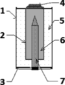
Alkaline cells are manganese dioxide-zinc (MnO2–Zn) cells with an alkaline electrolyte. Compared to chloride electrolyte batteries, alkaline batteries are able to deliver much higher currents at low voltage drops, making them suitable for applications where high current loads are required (toys, digital cameras…). Of course, they are also used in installations with low current leakage, especially where it is important to protect the device from electrolyte leakage. The steel cell holder is a positive pole, does not serve as an electrochemically active material and therefore does not participate in electrochemical reactions, which virtually eliminates the possibility of electrolyte leakage due to its corrosion.
In an alkaline cell, zinc powder serves as the negative electrode, manganese dioxide as the positive electrode, and potassium hydroxide as the electrolyte:
Negative electrode:
Positive electrode:

1 – Metal case
2 – Separator
3 – Plastic cap
4 – Metal cap (+)
5 – MnO2 and carbon powder
6 – Zinc and electrolyte (gel)
7 – collector electrode (–)
2 MnO2 + Zn → Mn2O3 + ZnO
Sometimes the subsequent reaction of ZnO with the KOH electrolyte is taken into account in the overall reaction, but does not affect the resulting electrical voltage (no change in oxidation number):
The alkaline cell is rated at 1.5 V. The new uncharged alkaline cell shows a voltage of 1.50–1.65 V. The average voltage under load can be 1.1–1.3 V. For example, a classic pencil alkaline cell (type AA) is generally designed for a rated current of up to 700 mA.
The comparison of equations (1), (2) and (3) shows that the advantage of alkaline cells is the higher utilization of MnO2 due to the reduction of Mn4+ to Mn2+, while in a slightly acidic electrolyte battery the process stops at Mn3+.
Electromotive voltage and source resistance
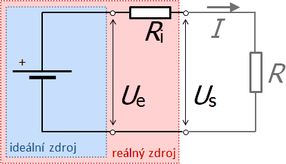
Based on the behavior of a real source, we represent it as a system consisting of an ideal source connected to a certain resistance inside the source. Each source is characterized by the so-called electromotive voltage Ue (voltage of the ideal source) and the internal resistance of the source Ri (resistance connected in series with the ideal source). The internal resistance influences the behavior of sources in circuits. It causes the voltage at the terminals of the power supply (terminal voltage) Us to be different from the electromotive voltage after the power supply is connected to the circuit. According to Ohm's law, the terminal voltage is lower than the electromotive voltage by the magnitude of Ri·I, where I is the electric current in the circuit.
Therefore, if we connect the source to a circuit with a resistor of R, a current of I flows, whose magnitude is given by Ohm's law for a closed circuit.
The relationship for the terminal voltage Us:
From relation (5) it follows that if the supply of the circuit does not deliver any current (I = 0), the terminal voltage is equal to the electromotive voltage (Us = Ue). On the other hand, when Us = 0 (i.e. when R = 0 – source short-circuit), the maximum short-circuit current flows through the circuit, which is limited only by the internal resistance (it follows from relation (4)):
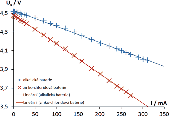
The above figure shows the dependence of Us = Us(I ) on the current flowing through the circuit for two different types of sources (alkaline and zinc chloride). According to relation (5), these are lines with different slopes, which are given by the internal resistance Ri (given by the construction of the source). In both cases they are so-called linear sources.
The basic parameters of the source can be deduced directly from the dependencies:
Ue – the value of the electromotive voltage as the value of the terminal voltage at I = 0;
Ik – short-circuit current as the value of the electric current at the short-circuited source (i.e. when Us = 0 V, see equation (6));
Ri – internal resistance of the source as the value of the dependency directive
(
).
The series of measured values of given dependencies can be transposed very well by linear regression. The individual regression coefficients then correspond to the parameters of the sources Ue and Ri – see expression (5). You can use a spreadsheet program (MS Excel, Oo Calc, Google Tabs, etc.) to quickly obtain the regression equation. The short-circuit current can be obtained not only by means of the equation (6), but also by the so-called extrapolation method. This method is based on the fact that by extending the regression line we find the intersection of Us = Us(I ) with the horizontal axis – the value of I for which Us = 0 (i.e. the short-circuit current Ik).


