Theory
Electroluminescent Diode (LED)

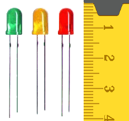
source: http://it.wikipedia.org/wiki/ File:Diodos_LED_foto.png
Light Emitting Diodes are semiconductor lasers in addition to the basic optoelectronic light source. Features luminescent diodes (LED = Light Emitting Diode) is based on electroluminescent phenomenon, which we understand the emission of a photon in the field of semiconductor PN junction, through which the current. By applying an external voltage to the PN junction in the forward direction occurs because of the injection (injection) minority carrier current to conductive areas. Part P of the electrons and holes in the area of bright N recombine with majority carriers and the energy released by emission of light occurs. This is also known as injection electroluminescence.
The band spectrum of radiation diode depends on the chemical composition of the semiconductor. LEDs are made with bands from ultraviolet radiation, different colors of the visible spectrum to the infrared band. Since the radiative recombination of an electron from band to band returns vodivostného valence, the energy quanta emitted light near the band gap width Eg.
Light-emitting diode features
Volt-Ampere Characteristics
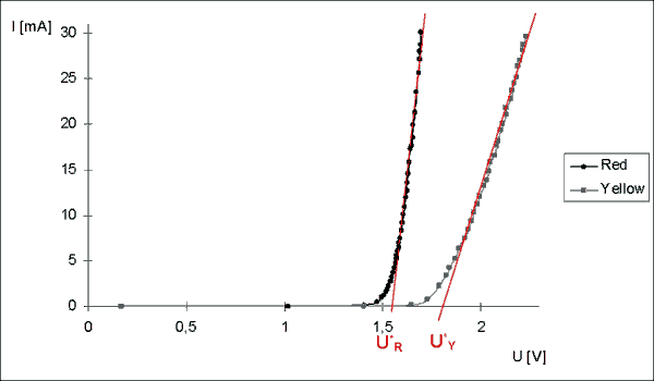
Properties of Light Emitting Diodes as Components of Electrical Circuits Volt amperes describe their characteristics. All light-emitting diodes typically have a diode waveform (see Figure 1).

Fig. 1 – Volt-Ampere Characteristics of red (RED) and yellow (YELLOW) electroluminescent diodes
Voltampere characteristics in the forward direction, it can be quite difficult to express the analytical formula:
| that: |
IF |
[A] |
– PN junction current flowing |
|
RS |
[Ω] |
– diode series resistance |
| I0 |
[A] |
– residual current |
|
T |
[K] |
– Absolute temperature |
| e |
[C] |
– electron charge |
|
n |
|
– see below |
| UF |
[V] |
– voltage on the diode |
|
k |
[J·K–1] |
– Boltzmann constant; k = 1,38 ·10–23 J·K–1 |
However, if the e.UF ≥ 4 k.T (i.e. when it is at room temperature for UF ≥ 100 mV) while UF >> IF·RS, simplify this equation to the form:
The shape characteristics depend on the geometry and properties of the transition, the properties of the material, the manufacturing technology, etc. All these factors are included in the dimensionless constant n. The reciprocal value of n defines the constant α = 1/n, which characterizes the mechanism of the charge transport transition (diffusion, recombination, tunneling).
Serial Static and Dynamic Resistance
As with any other semiconductor diode, the static series resistance (operating point UFo, IFo) can also be defined as:
and serial dynamic (differential) resistance, which is defined by:
Static resistance is on the order of 10–100 Ω, the dynamic resistance is < 1 Ω.
The Threshold Voltage
Another parameter is the threshold voltage U*, which is extrapolated from the linear part of the VA characteristic (red in Figure 1). When this voltage is linearized to break the dependence on the current flowing in the diode, a voltage is applied to the LED. This threshold voltage depends on the material from which the LEDs are made and is close to the diffusion voltage Ud, which is the width of the band gap Eg/e. The reason for this is that it provides a voltage U*, roughly speaking, carriers of the current energy necessary to overcome the potential barriers e·Ud. For GaAs diodes (Eg ≈ 1.4 eV), the threshold voltage U* is about 1.4 V; for GaAsxP1-x (Eg ≈ 1.4–2.4 eV, depending on the composition), U* = 1.4–2.3 V; for GaP diodes (Eg ≈ 2.3 eV), U* = 2.4 V.
The wavelength of the emitted light
A similar relationship exists between the threshold voltage and the radiated frequency (wavelength) of the emitted light. Shortening the wavelength of the emitted light increases the required power and the resulting voltage. While the classical (lightless) silicon diode rectifies this voltage with about 0.6 V, the green LEDs from GaP require 1.7 V and a blue LED from SiC even 2.5 V.
Considering that the energy released during recombination is converted into the energy of the emitted photon, we can write:
| that: |
e |
[C] |
– electron charge |
|
λ |
[m] |
– wavelength of the emitted photon |
| U* |
[V] |
– threshold voltage |
|
c |
[m·s–1] |
– speed of light; c = 3 ·108 m·s–1 |
| f |
[Hz] |
– frequency of the emitted photon |
|
h |
[J·s] |
– Planck's constant; h = 6,625 ·10–34 J.s |
| Color |
λ / nm |
| red |
656 - 768 |
| yellow |
568 - 585 |
| green |
495 - 535 |
| blue |
452 - 485 |
Tab. 1 - wavelengths of LEDs colors
Typically, knowing the threshold voltage U* determines the wavelength of the emitted radiation, which is compared to the tabulated values. Equation (4) can be used either way to estimate the magnitude of the Planck's constant. Knowing the threshold voltage and the approximate wavelength (see Table 1.) can be expressed in terms of Planck's constant:


