Theory
- NOTE:
- Derivations of expressions for diffraction maxima (or minima) at the slit, double slit and grating are given here at the secondary level. If you want to learn more about the derivation of these formulas and see the "correct" derivation of the formulas, you can study the following material: Studium difrakčních jevů – TEORIE – doplněk (in Czech language only).
Diffraction of Light
The bending of light (or diffraction) was first observed and described around 1660 by the Italian mathematics teacher Francesco Maria Grimaldi. In a darkened room, he allowed sunlight to fall through a small opening and placed various objects in the path of the resulting light to study their shadows. He discovered that the shadows were blurred and that they were also bordered by coloured stripes.
The basic assumption of ray optics, that light travels in a straight line according to the law of straight-line propagation, is only valid to a limited extent. In fact, the propagation of light, like that of any other wave (e.g. the propagation of sound waves), is affected by its wave properties. We can see this very clearly with obstacles that are comparable to its wavelength. In this case, the light is bent at the obstacle – this is called diffraction. This is manifested by the fact that the light partially spreads into the space behind the obstacle, where it should never spread according to ray optics, i.e. the light also spreads into the geometric shadow area. The boundary between light and shadow is then not sharp and a so-called bending (also called diffraction) pattern is formed on the shadow behind the obstacle.
Classification of Bending Phenomena
Bending phenomena are generally classified into two basic types:
When light is incident on an obstacle from a point source at a finite distance from the obstacle, these are Fresnel phenomena.
If the source (and the detector screen) are at infinity, then the waves coming from the source are plane and the phase of the oscillations is the same at all points of the obstacle (assuming the waves are incident perpendicular to the obstacle). The condition of an infinitely distant source (or shield) is achieved in practice by using lenses placed in front of and behind the obstacle. In this case, we are dealing with Fraunhofer phenomena. Fraunhofer placed a bending obstacle near the lens used to image a point or slit light source and studied the bending phenomena in the geometric image plane. By decomposing light using an optical lattice, he laid the foundation for lattice spectroscopy.
We will continue to study only Fraunhofer diffraction.
Light diffraction at a Slit
Suppose a plane light wave of wavelength λ is incident on a slit of width a. According to Huygens' principle, each point of the slit becomes a source of elementary waves, which propagate from it in elementary wavelets into the space behind the obstacle. Light is then incident from every point of the slit on every point of the screen. Since the slit has been illuminated by a plane monochromatic wave, these elementary waves can be considered coherent and a bending pattern is formed on the screen (see Figure 1).
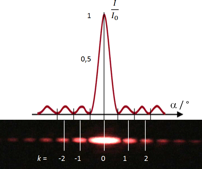
Fig. 1 – Light Intensity in a Bending Pattern on a Slit
(top: graph of intensity waveform; bottom: real pattern)
The plane wave hits the slit where the wave bending occurs. At the detection screen, the beam waves have different phases depending on the path they traveled to get there. The mutual stacking of these coherent wave beams produces the diffraction pattern mentioned above.
We now derive the condition for the appearance of interference minima of the diffraction pattern on the slit. A plane wave of wavelength λ is incident perpendicularly on a slit of width a. Rays from the whole slit space are incident on the given point. For the sake of clarity, only the rays coming from the edges of the slit (points A and B) are shown in the figure. The intensity of the light at point P (distance y from the slit axis) is shown by the red curve. The situation is shown in Figure 2.
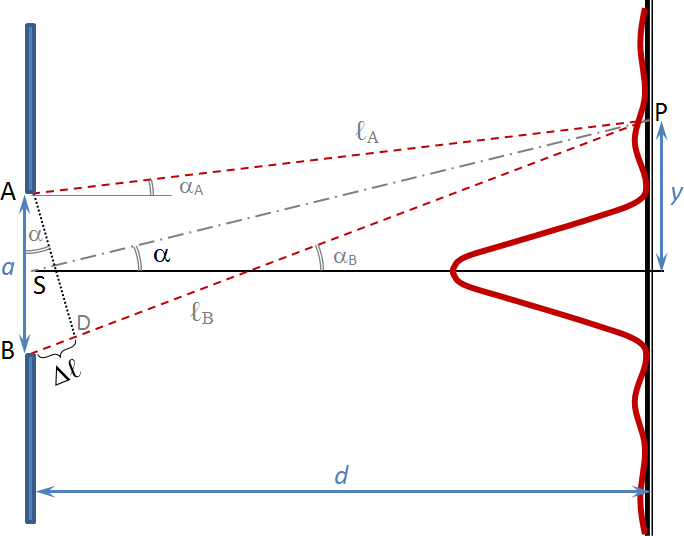
Fig. 2 – Derivation of the interference condition of the minimum at the slit.
The difference in trajectory between the wave propagating from point A (the top of the slit) and the wave propagating from point B (the bottom of the slit) is Δℓ (shown in Figure 2; see Note 1). Thus, the difference in trajectory between the wave propagating from the center of the slit S and the wave propagating from point A is Δℓ/2 due to the similarity of the triangles. Due to the axisymmetry of the ray bundle pointing from the entire slit surface to point P (the axis is shown in black in the figure), for every ray propagating from any point between A and S, there is a ray propagating from the points between B and S that is delayed by Δℓ/2. The interference minimum condition states that all waves will cancel each other out if this path difference Δℓ/2 is equal to an odd multiple of half waves. If we modify this condition for the entire path difference Δℓ, then it must be equal to an even multiple of half waves (twice the odd multiple is an even number).
To simplify the calculation of the path difference of the wavesℓA and ℓB, we have assumed that the shield distance d is much larger than the slit width a. Then the angles αA and αB are approximately equal (denoted α) and the directions of the two waves can be considered parallel, and the path difference of the paths ℓA and ℓB is given by the distance Δℓ. (In the figure, of course, it does not look like this because the condition a << d is not satisfied).
We can also see from Figure 2 that the path difference of the waves Δℓ can be expressed from the right triangle ABD, whose hypotenuse is the width of the slita, the path difference Δℓ being the subtended opposite of the angle α.
Thus, the path difference implies geometry:
We know from wave optics (or from the reasoning derived above) that the path difference for the minimum condition must be equal to twice the odd multiples of half the wavelength.
So we write the condition for the position of the bending minima:
which can be modified to form:
| where: |
a |
[m] |
– slit width |
| λ |
[m] |
– wavelength |
| α |
[°; rad] |
– angle (direction) at which the given minimum occurs |
| k |
|
– an integer other than zero
(for k = 0 the main bending maximum occurs!) – see Note 2 |
The maxima then occur between the given minima – marked in white in Figure 1 and with the given values of k (so-called orders of maxima).
In some texts dealing with diffraction at the slit, relation (1) is presented as a condition for diffraction maxima on the basis of an erroneous derivation of the ray path difference between points A and B. But this is not true! It is probably due to the similarity of the derivation (and also the similarity of the relation) for the condition of the maximum on the diffraction grating. The validity of the erroneous conclusion that relation (1) is a condition for the maximum is erroneously illustrated in some texts by showing that the relation correctly determines a zero-order maximum. This may be true, but unfortunately zero order is the only maximum that the relation correctly determines in this case! Condition (1) is indeed (and experimentally supported) a condition for first and higher order minima (k = 1, 2, …). Setting k = 0 is physical nonsense, because there are no zero minima in the diffraction pattern!
Light Diffraction at Multiple Slits
The most pronounced diffraction patterns are produced when light falls on multiple narrow slits. A system of many slits is called an optical grating (see below). The parameters of the array of slits are the slit width a and the distance between the centers of adjacent slits b – called the grating constant (or grating period) for a grating.
To derive the condition for the interference maximum on the grating, we first derive a relation for the bending of light on a system of two slits (called a double slit).
Diffraction at the Double Slit
Let the mono-frequency light from the distant source fall on the double slit. Again, we assume that the width of the slit a and the distance between the centers of the adjacent slits b are much smaller than the distance of the screen d from the pair of slits. Two phenomena occur when a plane wave is incident – diffraction at each slit (see above) and then also interference of two coherent waves from the two slits.
The light again propagates in all directions beyond the slits. In the same way as at a slit, we consider rays that have diverged by an angle α from their original direction, meet at point P and emerge from corresponding points – as shown in Figure 3. The corresponding points are the upper edges of the first and second slits (their mutual distance is b).
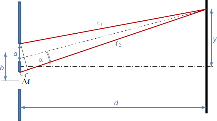
Fig. 3 – Derivation of the interference maximum on the double slit.
The figure then shows for the path difference of these rays ℓ1 and ℓ2:
| where: |
Δℓ |
[m] |
– path difference |
| b |
[m] |
– distance between slits |
| α |
[°; rad] |
– deviation of the wave from the original direction of the plane wave |
Amplification occurs in directions where the path difference is an even multiple of half-waves.
The maximum interference condition for a double slit is:
| where: |
b |
[m] |
– distance between slits |
| λ |
[m] |
– wavelength of the light used |
| α |
[°; rad] |
– angle (direction) where the maximum occurs |
| k |
|
– integer (so-called order of the maximum) |
The interference minimum occurs in directions where the path difference is an odd multiple of half-waves.
The resulting bending pattern at the double slit will still be affected by diffraction at the slits themselves, as mentioned above. Thus, the resulting pattern will be a composite of broader maxima and minima corresponding to the bending at one slit (the envelope curve) and a series of bright and dark bands resulting from the interference of light waves from the two slits ("modulation" of the pattern – see Figure 4; right part). Thus, the narrow equidistant bands can be said to result from interference from the individual slits, while the broad light and dark bands are the result of diffraction across the width of the slit.
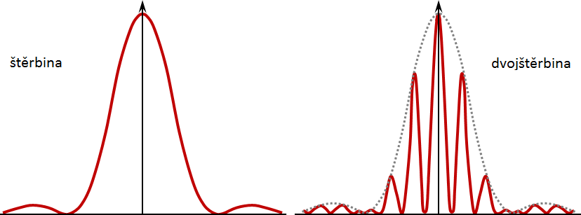
Fig. 4 – Diffraction pattern comparison for a single slit (left) and a pair of equal width slits (right).
Diffraction of light on the grating
The grating can be thought of as a system consisting of a large number of slits placed at equal distances b. Each of the slit points can be thought of as a point source of light, from which the light propagates according to Huygens' principle. From the analogy to the double slit (see above) follows for the path difference of the corresponding slit points of the grating the same relation for the interference maximum as for the double slit. The following figure illustrates the nature of the diffraction pattern for different numbers of identical slits. Note that for two or more slits, the positions of the maxima (or minima) do not change, only the area of the minima widens and the width of the maxima narrows ("focusing" of the maxima).
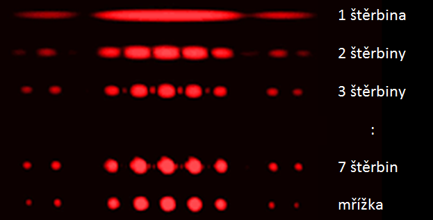
Fig. 5 – Comparison of diffraction patterns for different numbers of slits (1, 2, 3 … 7) and gratings.
The condition for the interference maximum on the grating corresponds to the condition for the double slits, except that the maxima are "sharper" in the case of the grating (see Figure 5):
| where again: |
b |
[m] |
– grating constant |
| λ |
[m] |
– wavelength of the light used |
| α |
[°; rad] |
– angle (direction) at which the maximum occurs |
| k |
|
– integer (order of the maximum) |