Commands and management
Communication between the controller and the application website K8055-MARIE is implemented using the JavaScript XMLHttpRequest module and the procedure itself uses the AJAX methods. This is the combined use of JavaScript module, which is implemented in modern web browsers, the client-side and supporting PHP scripts running on the server side. With this way of proceeding is not necessary to install any client side extensions as necessary environment for running Java applets, or elements of different extensions ActiveX.
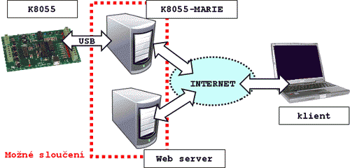
Remote management is implemented classic web page written in HTML language, extended with JavaScript commands to communicate with the K8055 board (see Fig. 1). These commands are stored in an external file K8055.js, which is given to the website connects just like any other javascript file. AJAX method is mediated by the standard JavaScript library jQuery for reasons of compatibility for different types and versions of Internet browsers. It adds security and reliability of communication.

Figure 1 - Diagram of communication by the client and server
Expansion JavaScript commands for K8055
Library of commands K8055.js
We attach the JavaScript library of the control-commands to a Web page by using files jQuery.js and K8055.js in the section <head>...</head>. These files are stored in folder jvs in the sample demo file.
The code of the sample file K8055-MARIE_demo.htm, looks like this:
		<!DOCTYPE html>

		<html>

		<head>

		<meta http-equiv="content-type" content="text/html; charset=UTF-8">

		<!-- BEGIN - JavaScripts for Remote Control -->

		<script src="jvs/jquery.min.js"></script>

		<script>

		   var MARIE_URL = 'http://K8055-MARIE_IP:PORT';

		</script>

		<script src="jvs/K8055.js"></script>

		<script>

		   SetCurrentDevice(K8055-ADR);

		</script>


		<!-- END - JavaScripts for Remote Control -->

		:

		atd./etc.
The file jquery.min.js is a jQuery library that extends the HTML page for general instructions AJAX-Communications. File K8055.js expands the web page on commands for a remote control of the K8055 board. Before you load the library K8055.js, you must set the IP address (or URL) of the computer, where is running the K8055-MARIE application, in the variable MARIE_URL (including the configured port). This value is here represented by the formal value http://K8055-MARIE_IP:PORT. If the variable MARIE_URL is not set, the default value http://127.0.0.1:80 is inserted into it by the library K8055.js - it means so-called localhost. It is a good idea to set the address our controlled USB board after loading the library K8055.js. To do this, use the SetCurrentDevice() command, with the parameter (here labeled K8055-ADR), the value is 0-3 - based on the address of the board used (set with switches directly on the board).
The control commands can be called by a standard JavaScript event (eg. page loads, click on the element, timer expires…etc.). Creation of a control website is the full responsibility of its creator.
- Example
- Sample of a web element (button) which when clicked sets all digital outputs on the K8055 board logic value 1:
<input type="BUTTON" value="Turn on outputs"" onClick="SetAllDigital();">
Commands from library K8055.js
Commands are trying (by their syntax) correspond with the original commands used in the DLL commands firm Velleman. New commands have been added for the purpose of enhanced and faster remote control from version 2.00. Command Reference of the library K8055.js is given in the table below.
K8055D.DLL v5.0.0.0 - K8055D.DLL v5.0.0.0 - Technical Manual - Czech translation
Description of the functions and procedures contained in the DLL library K8055D.DLL for direct control of USB board K8055 (Czech translation, the original English text on the website of Velleman).
The following table shows a list of commands javascript library K8055.js, including their descriptions:
K8055-MARIE (ver. 1.00 → x.xx)
Description of the command
ReadAnalogChannel(Channel)
The function returns an integer (0-255) corresponding to the voltage on the analog input. Variable Channel indicates whether the input 1 or 2
Example: (read analog input 1 to the variable AD1)
var AD1 = ReadAnalogChannel(1);
This function returns a character string composed of a pair of numbers corresponding to the voltage on the analog inputs. Both values are separated by |.
Example: (convert the output string to numeric variables hod1 and hod2)
var vyst = ReadAllAnalog();
var hod = new Array(2);
hod = vyst.split('|');
var hod1 = parseInt(hod[0]);
var hod2 = parseInt(hod[1]);
OutputAnalogChannel(Channel, Data)
Analog output - variable Channel determines whether the output 1 or 2 A numeric variable Data (0-255) determines the value of the output voltage (or width modulated signal)
The function returns true in the successful output settings (or false for failure).
SetAnalogChannel(Channel)
Sets the analog output (variable Channel) to the maximum value 255
The function returns true in the successful output settings (or false for failure).
Note:
same as the OutputAnalogChannel(Channel, 255)
ClearAnalogChannel(Channel)
Sets the analog output (variable Channel) to the minimum value 0
The function returns true in the successful output settings (or false for failure).
Note:
same as the OutputAnalogChannel(Channel, 0)
OutputAllAnalog(Data1, Data2)
Sets both analog outputs to the specified variable values Data1 and Data2.
The function returns true in the successful outputs settings (or false for failure).
Sets both analog outputs to the maximum value 255
The function returns true in the successful outputs settings (or false for failure).
Note:
same as the OutputAllAnalog(255, 255)
Sets both analog outputs to the minimum value 0
The function returns true in the successful outputs settings (or false for failure).
Note:
same as the OutputAllAnalog(0, 0)
SetDigitalChannel(Channel)
Sets a specified bit (variable Channel) from the set of eight digital output lines to logic 1 (ie the output terminal status ON).
The function returns true in the successful output settings (or false for failure).
ClearDigitalChannel(Channel)
Sets a specified bit (variable Channel) from the set of eight digital output lines to logical 0 (ie the output terminal status OFF).
The function returns true in the successful output settings (or false for failure).
Sets the bits set of eight digital output lines corresponding to the values of binary numbers specified variable Data.
The function returns true in the successful outputs settings (or false for failure).
Sets all digital output lines to logic 1 (ie the output terminal status ON).
The function returns true in the successful outputs settings (or false for failure).
Note:
same as the WriteAllDigital(255)
Sets all digital output lines to logical 0 (ie the output terminal status OFF).
The function returns true in the successful outputs settings (or false for failure).
Note:
same as the WriteAllDigital(0)
ReadDigitalChannel(Channel)
Returns the value true (or false) if at the time of query pressed one of five (defined variable Channel) digital inputs.
Returns the integer value of compiling pressed digital inputs. (First Input: 1, second: 2, third: 4, fourth: 8, fifth: 16)
Example: (status unmasking of digital inputs)
var pom = ReadAllDigital();
if ((pom & 1) != 0) {1st input IS pressed}
   else {1st input is NOT pressed};
if ((pom & 2) != 0) {2nd input IS pressed}
   else {2nd input is NOT pressed};
if ((pom & 4) != 0) {3rd input IS pressed}
   else {3rd input is NOT pressed};
if ((pom & 8) != 0) {4th input IS pressed}
   else {4th input is NOT pressed};
if ((pom & 16) != 0) {5th input IS pressed}
   else {5th input is NOT pressed};
Returns the value (0-65535) of the one of the two counters (digital inputs 1 and 2). Counter number is determined by the variable CounterNr.
Counter registers since it was reset and responds only to the desired pulse length (see below).
Resetting the counter 1 or 2 (determined by variable CounterNr)
Function returns true in successfully reset the counter (or false for failure).
SetCounterDebounceTime(CounterNr, TimeDebounceTime)
Setting the minimum pulse length in milliseconds (an integer variable TimeDebounceTime), which will be registered with the specified counter 1 or 2 (variable CounterNr).
Function returns true in the successful counter settings (or false for failure).
All of the commands listed in the table were (from version 2.7) extended by an optional parameter callback - is described below. The above commands are backwards compatible with lower versions (of course, without the parameter callback).
The commands in the following table are valid only from version 2.5 (without callback) and 2.7 (with callback).
K8055-MARIE (ver. 2.7 → x.xx)
Description of the command
– Note.: The parameter in [ ] is optional
SearchDevices([callback])
It returns a string composed of addresses (0-3) of the USB K8055 boards connected to PC and allowed by application K8055-MARIE (Addresses of the boards are separated by symbol: | ).
Note: The parameter callback is explained at the end of the table
SetCurrentDevice(CardAddr)
It sets the board of the specified address CardAddr (0-3) as the recipient of next commands.
Function returns true in the successful board settings (or false for failure).
ReadBackDigitalOUT([callback])
It returns a read back the value (0-255) of digital outputs, which is currently set to USB output boards (USB board is specified by command SetCurrentDevice()).
Note: The parameter callback is explained at the end of the table
ReadBackAnalogOUT([callback])
It returns a string composed of a pair of back-read values (0-255) of analog outputs of the USB board (Output values are separated by symbol: | ).
Note: The parameter callback is explained at the end of the table
ReadBothCounters([callback])
It returns a string composed of a pair of back-read values (0-255) of counters of the USB board (Counters values are separated by symbol: | ).
Note: The parameter callback is explained at the end of the table
Note:
It is a command that replaces a pair of commands
ReadCounter(1);
ReadCounter(2);
ReadAllInputs([callback])
It returns a string composed of a pair of back-read values (0-255) of analog outputs, value representing pressed digital inputs (see ReadAllDigital()) and a pair of back-read values (0-255) of counters of the USB board (All values are separated by symbol: | ).
Note: The parameter callback is explained at the end of the table
Note:
It is a command that replaces a series of commands
ReadAllAnalog;
ReadAllDigital();
ReadBothCounters();
It returns a string composed of the values of a complete state of USB boards (ie: analog inputs, digital inputs, counters, values of the analog outputs and digital outputs). All values are separated by symbol: |.
Note: The parameter callback is explained at the end of the table
Note:
It is a command that replaces a series of commands
ReadAllInputs();
ReadBackAnalogOUT();
ReadBackDigitalOUT();
GeneratorType(Channel, Type, [callback])
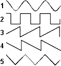
It sets the type (Type) of waveform (1 - sinus, 2 - square, 3 - ramp, 4 - sawtooth, 5 - triangle) that will generate (range 0-255) on the analog output Channel (1-2).
Function returns true in the successful board settings (or false for failure).
Note: The parameter callback is explained at the end of the table
GeneratorFrequency(Channel, Freq, [callback])
It sets the frequency Freq (0,01-10 Hz) of the waveform that will be generated on the analog output Channel (1-2).
Function returns true in the successful board settings (or false for failure).
Note: The parameter callback is explained at the end of the table
GeneratorTimeInterval(Channel, Time, [callback])
It sets time Time (1-300 s) of the duration of the waveform generated on analog output Channel (1-2).
Function returns true in the successful board settings (or false for failure).
Note: The parameter callback is explained at the end of the table
GeneratorStart(Channel, [callback])
It starts waveform generating (parameters described earlier) on the analog output Channel (1-2).
Function returns true in the successful board settings (or false for failure).
Note: The parameter callback is explained at the end of the table
GeneratorStop(Channel, [callback])
It stops waveform generating on the analog output Channel (1-2). (independently of any preset Time – see GeneratorTimeInterval())
Function returns true in the successful board settings (or false for failure).
Note: The parameter callback is explained at the end of the table
K8055_Json(cardAdr, [callback])
Control Application K8055-Marie sends status of the specified (cardAdr) board K8055 in a special JSON format readable for JavaScript. For example, the status of the analog output (no. 2) of the board K8055 (address 0) is then available in the variable: card[0].OUT.ANALOG.B
(see Note in section CallBack procedure)
The variable card is the array with indexes 0-3 (according to the addresses of connected plates K8055). The structure of this variable is as follows:
- Analog OUTs:
- card[0].OUT.ANALOG.A
- card[0].OUT.ANALOG.B
- Digital OUT:
- card[0].OUT.DIGITAL
- Analog INs:
- card[0].IN.ANALOG.A
- card[0].IN.ANALOG.B
- Digital IN:
- card[0].IN.DIGITAL.A
- Counters:
- card[0].IN.COUNTER.A
- card[0].IN.COUNTER.B
CallBack procedure
Parameter callback specifies the name of the JavaScript procedure that is performed after the successful completion of the function from library K8055.js (callback procedure is specified as a parameter).
For example,
We can choose between two options for writing values 155 to a digital output, and then display the information procedure, which, for example, is called ZapisVystup.
In the first case (standard):
WriteAllDigital(155);
ZapisVystupy();
Command1;
Command2;
the function WriteAllDigital(155) is called. The procedure ZapisVystupy will be executed after WriteAllDigital is completed. And after it is completed, Command1 and Command2 can continue (however, these commands may not be dependent on the two previous operations.) It can sometimes make a delay.
Conversely, when using the second listing:
WriteAllDigital(155, ZapisVystupy);
Command1;
Command2;
The commands Command1 and Command2 are executed immediately after WriteAllDigital(155), the procedure ZapisVystupy runs in parallel with these commands.
The functions for writing outputs and statuses of the K8055 are (from the version 2) solved as asynchronous, so write is done without any stopping of the following javascript code. If we use the above example with WriteAllDigital(155), Command1 and Command2 as an example, Command1 and Command2 will start immediately after calling the procedure WriteAllDigital(155) (not after it has been completed). The procedure ZapisVystupy must then be entered as a callback, because otherwise it would be started as soon as we do not yet know how the record was written. On the other hand, we often "only" need to write to the board without having to respond to the situation that has happened (then we do not need the function callback, so it is only an optional parameter).
On the other hand, the functions for reading inputs and state of the K8055 board are still solved synchronously. The first reason is backward compatibility due to version 1 commands, the second reason is simpler programming of synchronous code (especially for novice programmers). But the synchronous way significantly slows down the javascript code (it must wait for the K8055 board responding), so these commands have been supplemented with the function callback - so that at least the parallel processing of the result of the function can be performed while running the following code (possible use is completely optional).
Note:
An asynchronous function K8055_Json() has been developed to significantly accelerate K8055 readout, which fills the variable card without stopping the powerful code. If the update of this variable is solved on the background of the page using the function K8055_Json(), for example, using the timer event (the author of the script must resolve it), K8055 board input status queries can be significantly accelerated. The required value is retrieved from the variable card instead of synchronous polling using synchronous functions (see Version 1 tab). This method is fully asynchronous and fastest possible. However, it is recommended only after a thorough understanding of the asynchronous control philosophy and the flawless handling of K8055 remote control technology - So for experienced developers.


